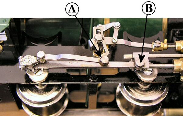
Fig 1
Roundhouse locomotives are available with either plain or insulated wheels. If you have a loco with plain wheels and later decide you need insulated ones, this is quite a straight foward job and can be done without upsetting the valve timing.
The following instructions apply to all of our outside framed, outside Walschaerts valve geared models. Although the pictures show an 0-4-0 model, the process is the same for 0-6-0 models but you have an extra axle to deal with.
Models with sprung axle boxes can also be done this way, but the axle boxes and springs will almost certainly fall out as you remove the axles. Don't loose any parts and they are easily pushed back into place as the axles are replaced. On the Vale of Rheidol locomotive, it is also necessarry to remove the slide bars and motion bracket on one side to allow the axle to slide out.
Step 1/
Remove the two 6BA hexagon headed crank pins on one side of the loco as shown in fig 1. Note that crank pin A has a small steel washer between the eccentric rod and expansion link. Crank pin B, which connects the connecting rod to the piston rod, also holds the dummy crosshead in place.
Fig 2 shows the rods disconnected.
Fig 1
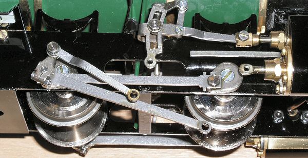
Fig 2
Step 2/
Remove the 4BA countersunk screws from the ends of the axles using a medium sized screwdriver. These are quite tight, so to stop the axle turning, you can either grip the axle (as hown in fig 3) or grip the ourside crank (as shown in fig 4).
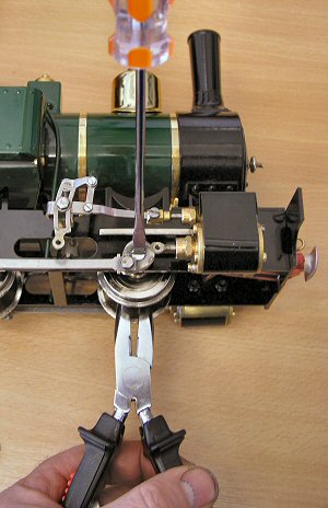
Fig 3
Step 3/
Remove the outside cranks complete with coupling, connecting rods and rear half of valve gear. These are a close fit onto the square ends of the axles and will require a little help to get them off. Grip firmly with a pair of pliers, as shown in fig 4, and rock it gently from side to side as they slowly ease off the square. Fig 5 shows the assembly removed.
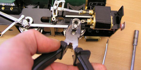
Fig 4
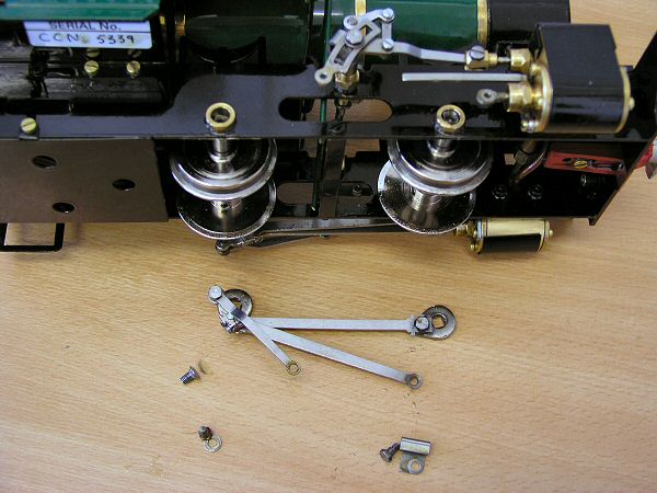
Fig 5
Step 4/
Turn the loco over and repeat step 1 only on the other side. Note that it is not necessarry to remove the outside cranks etc. from this side.
Step 5/
Place the loco on its roof and slacken the 4BA grub screws clamping the wheels to the axles.
Gently ease the wheels towards the ends of the axles from which you removed the outside cranks and, slide the axles out of the frames just enough to allow a wheel to be removed. See fig 6.
On the side where the outside cranks are still fitted, push the piston right forward and rotate the axles to get the front outside crank in a position where it will just move out past the end of the piston rod and slide bar.
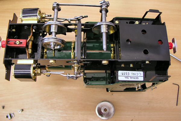
Fig 6
Step 6/
Slide all wheels off the axles then replace with the new ones. Note that insulated wheels tend to be a slighlty tighter fit on the axles than plain wheels and may require working onto the axles with a rotational movement. Dont forget that the bosses on the wheels are on the back and face each other.
Fig 7 shows the first insulated wheel being fitted to an axle.
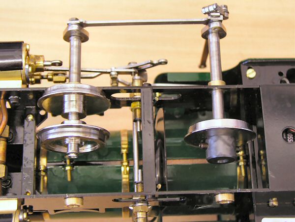
Fig 7
Step 7/
When all wheels are in place, slide the axles back through the frames.
Step 8/
Replace the outside cranks, making sure that the right hand side leads the left hand side by 90 degrees, then replace and tighten the 4BA countersunk screws that hold them in place. Make sure that these are nice and tight as they pull the cranks onto the square ends of the axles.
Step 9/
Re-connect the connecting rod (dont forget the crosshead) and eccentric rod, not forgetting the small steel washer.
Step 10/
Turn the loco over and re-connect connecting rod and eccentric rod on other side.
Step 11/
Set the wheel gauge using the back to back gauge as shown in fig 8. Position the wheels so that you have an equal gap each side between th outside of the wheels and the inside of the frames.
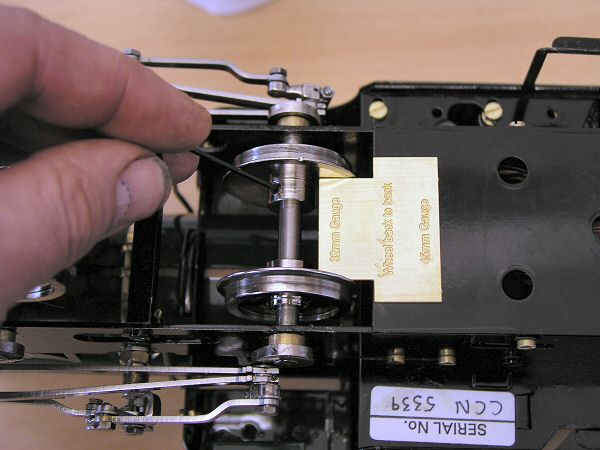
Fig 8
Roundhouse Engineering Co. Ltd., Doncaster, UK. 2018. Click Here To Return To The Homepage