Does not cover 'Basic Series' locomotives.
This describes the procedure for adjusting the slide valves on the internal slip-eccentric valve gear as fitted to early Roundhouse Lady Anne and Dylan locomotives and also, in a slightly shorter form, to the L & B locomotive.
Although the original version of this valve gear, as fitted to the non gauge-adjustable Dylan and Lady Anne models, had a different layout of eccentric and stop collar, the setting proceedure is the same for both.
Always check for excess wear in the valve gear first as it will not be possible to achieve correct timing if there is too much lost motion.
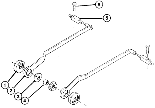
Slip-eccentric valve gear is very simple as shown in the diagram below. The stop collars are fixed to the drive axle by grub screws and these drive the eccentrics by means of a small drive pin which is pressed into the eccentric. The stop collar has a slot machined (either radially as show or accross one face on original version) which allows the eccentric to 'slip' freely on the axle for about half a turn of the wheels. In this way, the valve timing can altered simply by moving the loco in the desired direction with the steam regulator closed. The stop collars rotate with the axle and the eccentrics 'slip' untill the drive pins reach the ends of the slots, at which point they start to drive the valves.
1 - Stop collar. 2 - Eccentric rod. 3 - Eccentric. 4 - Spacer. 5 - Rocker arm. 6 - Rocker arm pivot screw.
Shown above is the later version of the slip-eccentric valve gear as used on adjustable gauge models. The earlier version for fixed gauge models is similar but the stop collars are on the inside (back to back) and the eccentrics are to the outside, just behind the wheels.
You will find it easier if you concentrate on setting one side at a time.
Remove the valve chest cover from the cylinder and replace a couple of screws to hold the valve chest in place. You can now look down into the valve chest and see exactly what happens.
Check the position of the slide-valve on the spindle by rotating the wheels and watching the valve movement.
As you rotate the wheels, the valve moves backwards and forwards over the steam ports. There are three steam ports under the valve though you will only ever see two of them, the inlet ports. These are the ports that allow steam to travel too and from the ends of the cylinders. The third port, the exhaust is always hidden under the centre of the valve and plays no part in the setting.
As the valve moves backwards and forwards, it should uncover both the inlet ports in turn and by the same amount. If it does not, adjust its position by unscrewing the rocker arm pivot screw, lift the rocker arm out of the valve spindle end socket, then screw the valve spindle in or out a little as required. This has the effect of moving the valve along the spindle. For instance, if the front inlet port was opening more than the rear one, then the spindle should be rotated anticlockwise to move the valve forward along its length. Replace the rocker arm and check the valve movement again. Repeat the operation until equal opening is achieved Note that when they are opening equally, the ports are not opening fully. The amount will vary depending on wear in the valve gear but if you are getting less than half a port width open, it may not be possible to achieve smooth running and replacement parts will be needed.
Timing the valves simply means ensuring that the correct port opens at the correct time, so that steam is admitted to push the piston along the cylinder just when its needed and conversely, is allowed to exhaust up the chimney when its done its work.
The valve timing is controlled by the stop collar on the drive axle.
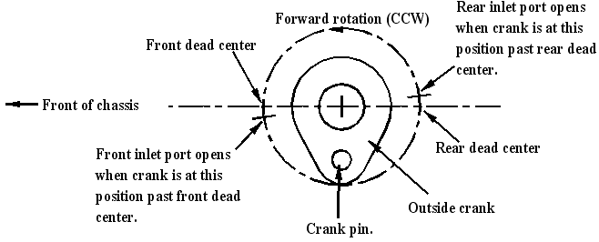
Left hand drive axle outside crank. Right hand side is mirror image of this
Refering to the diagram above, rotate the driving wheels in the forward direction until the crank pin on the drive axle outside crank on one side is a little after front dead centre. Note that when looking at the left hand side of the locomotive (as in diagram), forward rotation of wheels is anti-clockwise. When looking at right hand side of locomotive, forward rotation of wheels is clockwise.
Holding the wheels in this position, slacken off the grub screw holding the stop collar on the same side and, whilst looking down into the valve chest, rotate the stop collar on the axle in the same direction. Keep turning the stop collar until the front edge of the front port is just visible (cracking open as it is known) as the slide valve is moving backwards. Gently tighten the grub screw. Rotate the wheels in the same direction whilst watching the valve. The rear inlet port should just start opening as the crank pin on the same outside crank is a little after rear dead centre.
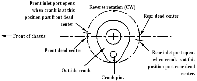
Now rotate the wheels in the reverse direction and check where the outside cranks are when the ports are just cracking open. This should again be a little after dead centre. The idea is to get both ports opening when the outside cranks are at the same position after dead centre in both forward and reverse rotation. The actual distance (degrees after dead center) will vary depending on the amount of wear in the valve gear.
All adjustment to achieve this is done by moving the stop collar a little at a time and re-checking.
Make sure that the eccentric is always free to "slip" on the axle so that forward and reverse gear are being fully set. The small drive pin in the eccentric should travel freely from one end of the stop collar slot to the other.
When all is correct, lock up the stop collar grub screw and replace the valve chest cover etc. Repeat for the other side.
Once you are happy with the visual settings, the valve chests can be closed ready for a steam test.
Squirt a little steam oil into the valve chest as you replace the top cover and gasket, to help lubricate and seal the valve. Note that the valve nut has a flat machined on it, which must be to the bottom when sitting it down into the slide-valve. If it is not, the valve spindle will lock up and may be damaged when the valve chest cover screws are tightened.
When the locomotive is capable of running on the track under its own steam, the timing can be fine-tuned for best performance.
Set the loco off on a reasonably level length of track at a slow speed. If it stalls, note the position of the drive crank pins and if either is at front or rear dead center. Repeat this several times and it will soon show up if there is a 'dead spot' at any particular point of the valve cycle. If, for instance, it keeps stalling with one particular crank pin just after rear dead center, then this would indicate that the slide valve is opening a little late. Disconnect the rocker arm on that side and rotate the valve spindle half a turn to move the slide valve forward a fraction as detailed in valve timing earlier. Reconnect the rocker arm and try the loco again in both directions to check that your adjustment has not simply removed that dead spot only to replace it one in a different position. A short time spent running the engine and making adjustments of just half a turn of the valve spindle at a time should soon show its optimum positions.
Roundhouse Engineering Co. Ltd., Doncaster, UK. 2018. Click Here To Return To The Homepage