Valve timing is very important and, if wrong, will cause jerky running or even the inability to run at all. Jerky running can be caused by many things, so don't jump to any conclusions before actually inspecting the loco. Firstly, it needs to be established if the jerking is caused by incorrect valve timing, or binding somewhere in the motion. It could be that something has got bent or come loose and is causing a tight spot or interference with another part.
A thorough visual check of the chassis should be carried out whilst rotating the wheels in both directions, looking and feeling for any tight spots and anything that may be causing this - bent rods, loose fastenings etc.. If this is not the case, then there are several things that could have upset the valve timing.
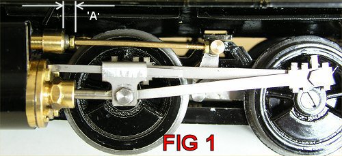
General wear will cause lost motion in the valve gear and linkages and will prevent the piston valve from moving the required distance. This has the effect of not only preventing full opening of the steam ports, but also altering the point at which the ports are opened and closed. On a new model, full valve travel is approximately 3mm and this can be measured at the back of the valve chest (distance A see fig 1).
The model will accommodate a certain amount of lost motion and the actual amount will vary between engines but, if you are getting substantially less than 3mm valve travel, this should be addressed. Points to check for excess clearance are:-
The only remedy for wear is to replace the affected parts
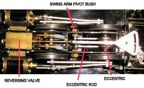
This has happened on a couple of early loco's. Check the brass bushes (one each side) that support the swing arm assemblies. These are bolted through the frame with a nut on the outside. If the bush comes loose or fractures then it allows the swing arm pivot to move backwards and forwards, thus upsetting the timing. Due to the thin wall ofthis bush, it must not be over-tightened or it is weakened and will fracture.
Later models have a thicker wall to help prevent this.
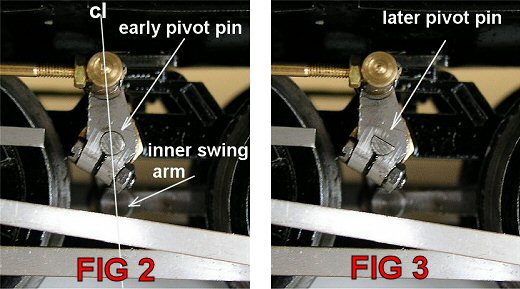
Again, this only affects early models that have a plain round pivot pin and the swing arms clamped on each end. They are a stainless laser cut and pretty hard so will normally clamp up nice and tight on the pivot pin but it is possible for these to become loose and rotate slightly on the pivot pin - upsetting the valve timing.
If you refer to fig 2, it illustrates this type and fig 3 illustrates the later design of self aligning swing arms for comparison.
If your engine is fitted with the early type, check alignment as in fig2 and, viewing the arms straight on from the side, imagine a centre line that passes through the valve rod pivot, the swing arm pivot pin and the eccentric rod pin.
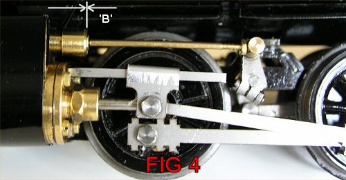
The timing is set visually to start with and fig's 1 and 4 illustrate what you are looking for. Check with pistons at mid stroke, as this places the valves at their front and rear dead centers. With the crank pins at the bottom (fig 4) the valve will be at its front dead centre and the rear face of the brass locknut will be flush with the rear end of the valve chest extension (distance 'B' on the photo). With the crank pins at the top, the valve will be at it's rear dead centre (fig1) and distance 'A' should be roughly twice the thickness of the lock nut.
For fine tuning, a good method is to connect the chassis/loco to an air supply and disconnect the connecting rods at the crosshead. Sit the loco on blocks so that the wheels are off the ground, put the loco in gear with the reversing valve and slowly rotate the wheels in the correct direction. If you watch the piston rods you will be able to determine the exact point at which they move in or out relative to the crank pin position, and make slight adjustments as needed. The cylinder should activate and move the piston rod when the drive crank pin has just passed a front or rear dead centre. As the crank pin passes rear dead centre, the piston should retract into the cylinder and, as it passes front dead centre, it should push the piston rod out of the cylinder. Be very careful to select the correct direction of running on the reversing valve, to match the direction of rotation of the wheels. Check this visually several times in both directions and adjust until the degrees after dead centre at which cylinder activation occurs, is roughly even in both directions.
If an air supply is not available, the same proceedure can be carried out under steam, but be very careful as the loc will get very hot in places.
There are three (two on later models) key points on the valve gear where adjustments can be made.
Roundhouse Engineering Co. Ltd., Doncaster, UK. 2018. Click Here To Return To The Homepage